

Withdrawable Switchgear Cabinet Solution for Modern Industrial Power Systems
2026-10-24
What if a single fault didn't have to mean a complete shutdown? In modern industrial power systems, withdrawable switchgear is redefining maintenance and scalability—but only when it's built right. MOLDVOLT brings a fresh perspective to this proven concept, addressing the hidden reliability gaps that many traditional designs overlook. In this article, we'll break down the key advantages and design choices behind a truly future-ready withdrawable switchgear cabinet.
Why Withdrawable Units Earn Their Place in Busy Switchrooms
Busy switchrooms demand equipment that can keep pace with daily operations, and withdrawable units answer that call without making a fuss. The ability to slide a breaker or contactor out on its own carriage means routine checks and part swaps happen in minutes, not hours. Instead of roping off half the room for a shutdown, technicians simply isolate one module, pull it forward, and get eyes on the contacts without disturbing the lineup. That kind of direct access turns what used to be a planned outage into a quick task between other jobs.
Another quiet advantage is how these units sidestep the usual space crunch. Fixed gear often needs extra clearance for tool swing and cable pulls, but a withdrawable design keeps all the working room on the front face. Rows stay tighter, aisles stay clearer, and the room doesn't feel like a puzzle box every time someone needs to trace a circuit. It's a layout that respects the fact that switchrooms are living spaces, not static displays.
Then there's the matter of confidence during faults. When a trip occurs, pulling the unit gives an immediate visual and mechanical isolation that a fixed breaker can't match on its own. You see the disconnects, you confirm the gap, and you lock out with a clear conscience. For crews that have learned not to trust a painted indicator alone, that physical separation is worth more than a dozen procedural reminders.
What Draw-Out Breaker Swaps Look Like During a Live Shift
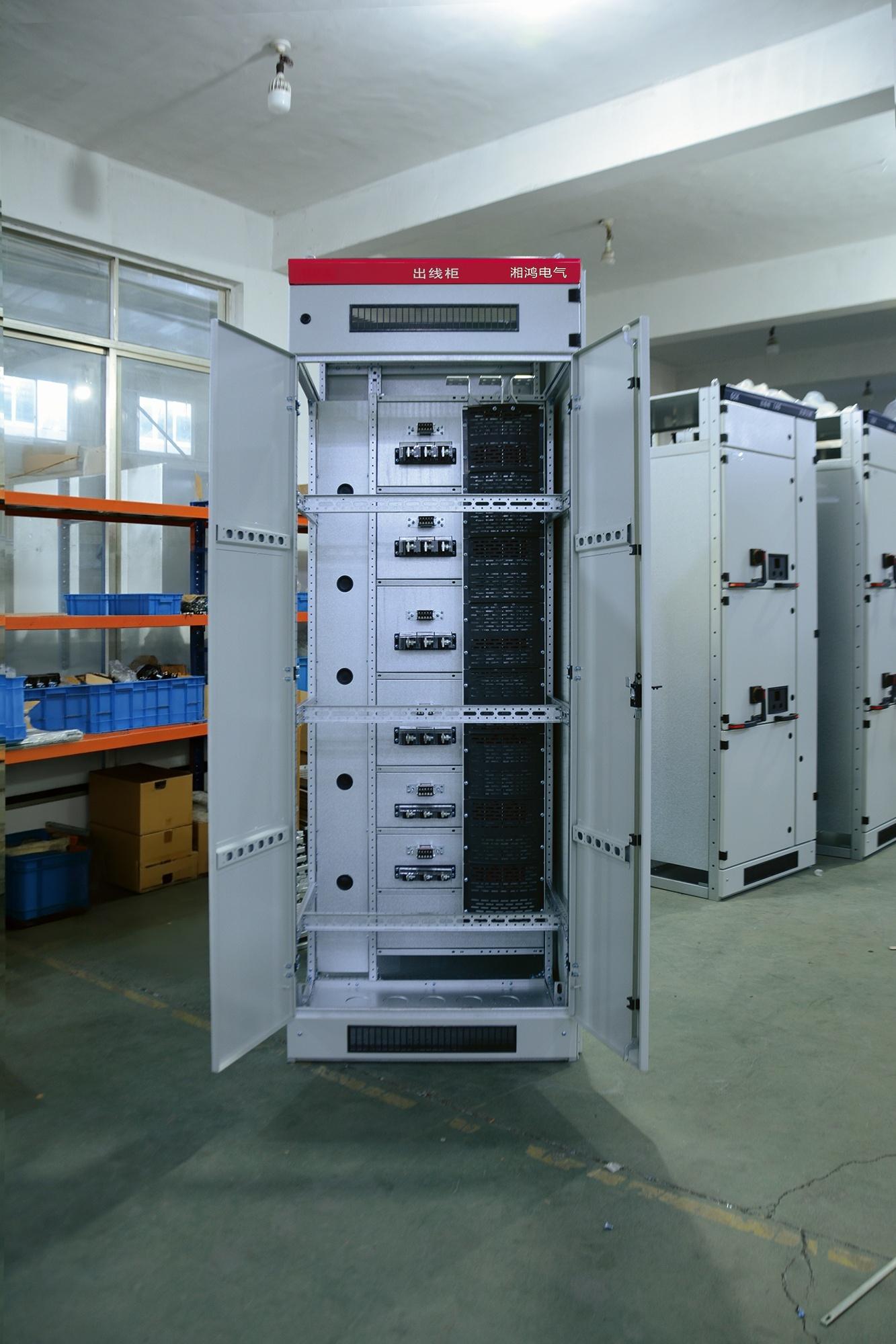
You pull the cubicle door open and the racking handle is already in someone’s hand, not because anyone rushed, but because the shift rhythm has everyone anticipating the next move. The breaker sits in the connected position, its position indicator showing red, and the first thing you do is trip it locally—none of that remote soft-trip stuff when you’re standing two feet from an arc flash boundary. The control plug gets pulled, then the secondary disconnect, and you check the shutter mechanism with your own eyes before anyone puts a hand near the racking screw. One person rack, one person watches the breaker’s flags and the bus stab alignment, and a third has the spare breaker already prepped on the transfer cart with the correct trip unit settings dialed in. It’s not a drill; it’s just what Tuesday looks like when a feeder has been running hot all morning.
The actual swap rarely takes more than ten minutes on the draw-out part, but the live-shift part means you’re doing it while other loads are still humming in the same lineup. You don’t kill the whole board for one 400-amp frame. You isolate the compartment, verify zero voltage on the stabs with a proximity tester even though the shutter is closed, and then rack to the test position before the final pull-out. New breaker goes in reverse: engage the racking mechanism slowly, feel for any binding, and listen for that distinct click when the secondary contacts seat. After the swap, you leave the old breaker on the cart with a red tag on the handle and a note taped to the front escutcheon saying exactly which feeder it came from and what the fault code was. The shift log gets a line or two, no more than that—the next crew can read between the lines.
Busbar and Compartment Design That Keeps Withdrawal Safe
Withdrawable circuit breakers have long been a practical way to isolate and service equipment without de-energizing an entire board, but the real test of that design lies in what happens when the breaker is rolled out. In well-engineered switchgear, the busbar chamber is fully segregated from the breaker compartment by steel or insulating barriers, and spring-loaded shutters drop over the fixed contacts as soon as the breaker begins to move. This means the live busbar stabs are never exposed, even if someone pauses halfway through the racking operation. The shutters are keyed to the breaker position, so they cannot be pushed open by hand or by a tool.
Behind the shutters, the busbar arrangement itself is laid out to minimize risk. Phase conductors are spaced and supported by molded insulators that maintain creepage and clearance distances even under thermal expansion or short-circuit forces. Busbar joints are torqued and covered with insulating boots, and the compartment is designed to vent arc gases away from the operator during a fault. For withdrawal, a mechanical interlock ensures the breaker can only be racked out when it is in the open position, and the racking mechanism often drives a visible position indicator. In some designs, an optional earthing switch can be interlocked so that it only closes after the breaker is fully withdrawn, adding another layer of protection for maintenance crews.
Setting Protection Relays for Motors, Feeders, and Mixed Loads
Protection relay settings for motors, feeders, and mixed loads cannot follow a single template. Motor circuits need thermal overload curves matched to actual nameplate current, locked-rotor protection that rides through normal starting, and phase unbalance detection set low enough to catch single-phasing. Feeder relays, on the other hand, prioritize time-current coordination with downstream devices, so a fault downstream clears locally instead of tripping the entire feeder.
A practical starting point for motors is to set the overload pickup at 105–115% of full-load current, using Class 10 or Class 20 trip curves depending on acceleration time. Short-circuit elements should sit above locked-rotor current but below the motor damage curve. For feeders, phase overcurrent pickups often start around 125–150% of maximum expected load, with ground fault settings lower—typically 20–40% of phase pickup—to catch high-impedance arcing faults without nuisance trips.
Mixed load circuits demand extra attention because motor inrush and transformer magnetizing currents can look like faults to a fast instantaneous element. Group loads by starting characteristics and apply a short time delay to instantaneous or definite-time elements, allowing asymmetrical inrush to decay. After any change in motor size, feeder length, or load mix, rerun the coordination study and adjust relay curves so selectivity holds under both normal starting and fault conditions.
Reducing Maintenance Lockouts Without Losing Selectivity
Traditional index maintenance often forces a choice between a fully rebuilt structure and a locked table. But newer approaches let you keep queries selective without freezing writes. Online rebuilds, for instance, handle most of the work while the old index remains available, only taking a brief schema lock at the end.
Partition-level operations push this further. Instead of locking an entire table, you can rebuild or reorganize a single partition, leaving the rest accessible. That is especially useful when only recent partitions change frequently and older ones stay static. The optimizer still sees accurate statistics for each partition, so selectivity does not drop.
Another angle is using filtered indexes or columnstore compression in the background. By creating a new structure alongside the old one, then switching names when it is ready, you avoid long maintenance windows. During the switch, queries may block for milliseconds, not minutes. This keeps histograms fresh and the plan quality high without resorting to full table scans.
Comparing Fixed and Withdrawable Cabinets Midsized Plants Actually Face
Choosing between fixed and withdrawable switchgear in a midsized plant rarely comes down to a single spec sheet number. Fixed cabinets take up less floor space and cost less upfront, but any breaker repair means opening the busbar compartment and working in tight clearances. Withdrawable units can be rolled out and swapped in minutes, yet the extra depth, plug-in contacts, and compartment interlocks add both capital cost and potential failure points. Many maintenance teams appreciate the withdrawable design on paper, but in practice they still schedule shutdowns for major work because they lack the spare cassettes or trained staff to do live swaps.
The real decision often hinges on how the plant handles downtime. If a production line can tolerate a few hours of planned outage, fixed switchgear with a spare feeder or two is usually the cheaper and more robust choice. However, when even a short interruption ripples through continuous processes—think extrusion, compounding, or cold storage—the ability to isolate and replace a single withdrawable module without de-energizing the whole board becomes a genuine operational advantage. That said, midsized facilities frequently overlook the clearance needed behind withdrawable panels. A cabinet rated for front access may still require rear space for cable termination, and older electrical rooms often cannot provide that without costly civil work.
Spare parts and standardization also weigh heavily. Fixed breakers are often simpler, with fewer moving interfaces, but they demand careful torque control and busbar alignment during reinstallation. Withdrawable cassettes depend on secondary contacts, guide rails, and shutters that need periodic inspection, especially in dusty or humid environments. A medium-sized plant without a dedicated switchgear specialist may find that a sophisticated withdrawable system degrades faster than a fixed one simply because the maintenance routines are not followed. The better choice is not universal; it depends on the actual outage budget, room dimensions, environmental conditions, and the skill level of the local electrical crew.
FAQ
The key difference is that the main switching device—typically a circuit breaker or contactor—is mounted on a movable carriage that can be racked in, out, or isolated without de-energizing the entire busbar system. This allows maintenance, testing, or replacement while other feeders remain live, reducing downtime and improving operator safety.
Because the breaker truck can be withdrawn to a disconnected, test, or fully removed position, technicians are not exposed to live busbar connections during routine work. The enclosure stays closed and grounded, and mechanical interlocks prevent racking the device in or out under load, which significantly lowers the risk of arc flash and electrical contact injuries.
Interlocks are crucial for enforcing correct operating sequences. They prevent inserting or removing the breaker unless it is open, block closing the breaker while it is in an intermediate position, and ensure the earthing switch cannot be operated unless the breaker is fully withdrawn. This kind of forced logic eliminates many human errors that could otherwise lead to severe faults.
Many modern withdrawable switchgear cabinets are tested for internal arc containment according to IEC 62271-200. They incorporate reinforced compartments, pressure relief flaps or ducts, and arc-resistant doors or covers. If an arc occurs inside, the energy is channeled away from the operator zone and exhausted through a controlled path, protecting personnel and adjacent equipment.
It really shines in continuous process industries such as chemical plants, steel mills, data centers, and large manufacturing facilities where unplanned downtime is extremely costly. The ability to swap a breaker or isolate a feeder without shutting down a whole switchboard makes it ideal for critical power distribution where redundancy and serviceability matter more than initial cost.
Beyond basic ratings like voltage, current, and short-circuit level, they should check the internal separation form (e.g., Form 3b or 4b), busbar material and plating, degree of protection, and whether the design allows future extension. Also consider the local service network and spare parts availability, because a highly specialized cabinet with no local support can become a liability.
The busbar system remains fixed and fully enclosed, while cable compartments are typically front-accessible and independent of the breaker truck. This means cables can be terminated, tested, or added without disturbing energized busbars. The withdrawable unit simply plugs into fixed contacts, so the cable side can be isolated and earthed for safe working.
The test position allows the control circuits to be fully energized and the breaker to be operated open/close while the main power contacts are disconnected. Engineers can verify protection relay settings, trip and close coil operation, interlocking logic, and SCADA signals without applying medium voltage to the primary circuit. This dramatically speeds up commissioning and reduces the chance of wiring mistakes going unnoticed until startup.
Conclusion
In many midsized plants, fixed switchgear forces a full shutdown for even routine breaker checks, but withdrawable cabinets change that. Draw-out units let operators physically separate the breaker from live busbars without de-energizing the whole board. During a live shift, a swap involves racking the old unit to the disconnected position, verifying the shutters close over the busbar stabs, then sliding in a tested spare. The compartment layout and grounded metal barriers are what make this safe; the breaker cannot be withdrawn unless it is open, and interlocks prevent racking a closed breaker onto a live bus. This cuts downtime from hours to minutes and keeps feeders running.
Protection settings need to reflect real load mixes. Motors often require thermal overload curves and stall protection, while feeders may need definite-time overcurrent, and mixed boards benefit from zone-selective interlocking rather than simple time grading. Withdrawable designs also ease selectivity work: instead of locking out a whole section to test one relay, technicians can isolate a single carriage and inject test currents on the bench. That reduces maintenance lockouts without flattening the protection curve. Compared with fixed cabinets, withdrawable gear costs more up front and takes slightly more floor space, but the ability to swap a faulty breaker while the rest of the plant stays energized usually pays for itself after the first avoided shutdown. For a busy switchroom, that operational headroom is the real difference.
Contact Us
Contact Person: Hellen
Email: [email protected]
Tel/WhatsApp: 86-13634205622
Website: https://www.voltcabinet.com